
Thermal Accumulators
February 9, 2022 | By John Siegenthaler
John Siegenthaler shares lessons learned and ways to use buffer tanks in systems supplied by heat pumps.
Whenever a hydronic system is divided into several zones it’s worth considering a buffer tank between the heat source and the distribution system. This is especially true when the heat source is a single speed “on/off” device rather than a modulating device.
One example is a 4-ton geothermal heat pump supplying several individually controlled panel radiators. Each radiator represents what I would call a “micro-zone.” The output of such a zone is likely less than 10%, perhaps even less than 5% of the heating capacity of the heat source. If you connect several such zones directly to a heat source, even one that can modulate down to say 20% of rated capacity, you’re likely to experience short cycling. This same reasoning holds true for an air-to-water heat pump.
Sizing a Buffer Tank
The size of a buffer tank is based on two parameters the designer chooses:
- What is the minimum run time of the heat source that avoids the designer’s definition of “short cycle?”
- And what is the allowable temperature change of the buffer tank during the minimum on-cycle time?
Once these two decisions are made, the math is easy. The minimum tank size can be determined by Formula 1.
Formula 1:
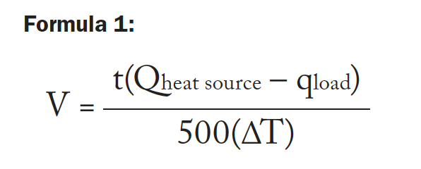
where:
V = required volume of the buffer tank (gallons)
t = desired duration of the heat source’s “on cycle” (minutes)
Qheat source = heat output rate of the heat source (Btu/h)
qload = rate of heat extraction from the tank (can be zero) (Btu/h)
∆T = temperature rise of the tank from when the heat source is turned on to when it is turned off (F)
Here’s an example. Assume that a designer wants a hydronic heat pump with a rated output of 48,000 Btu/h to operate with a minimum on-cycle of 10 minutes while supplying heat to a towel warmer radiator releasing heat at 2,000 Btu/h.
The heat pump responds to the buffer tank temperature. It turns on when the buffer tank temperature drops to 100F, and off when the tank reaches 120F. What is the necessary buffer tank volume to accomplish this?
Just put the numbers into the formula and grab a calculator:
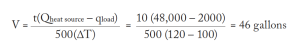
Larger buffer tanks can provide longer heat source on-cycles. They can also allow a narrower temperature change over a specific on-cycle. It’s easy to evaluate the trade-offs between on-cycle length and tank temperature swing using Formula 1. Large buffer tanks obviously cost more, take up more room, and usually have higher standby heat loss.
Making Connections
There are several ways to pipe buffer tanks. They are called “four-pipe”, “three-pipe” and “two-pipe” configurations. Figure 1 (below) shows all three.
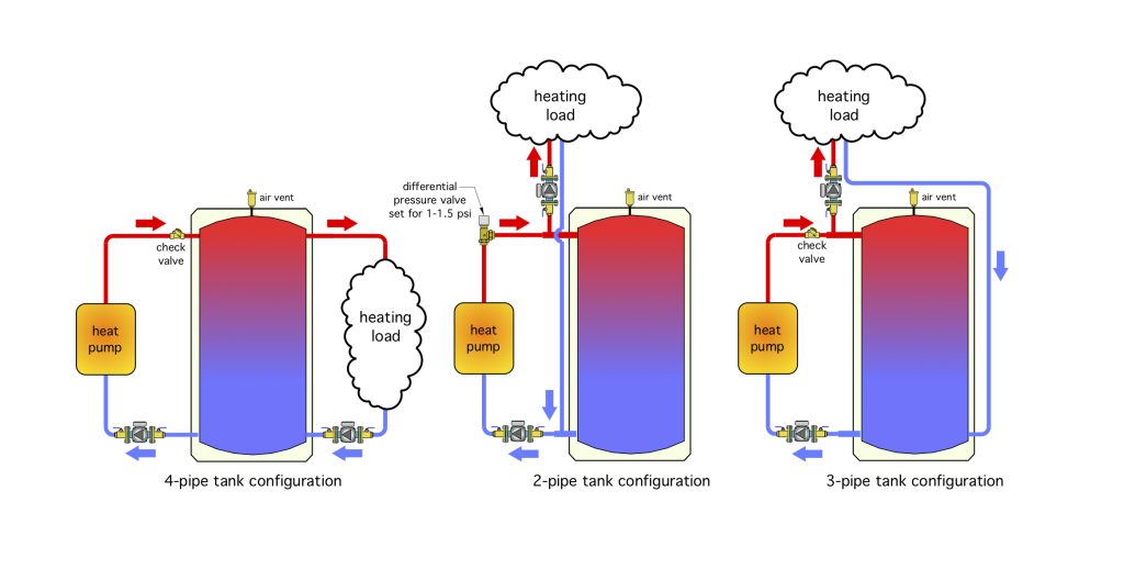
Figure 1. Two-, three- and four-pipe buffer tank configurations.
The four-pipe layout is the “classic” piping configuration for buffer tanks in hydronic systems. The heat source adds heat on one side, while the load removes heat from the other side. This piping configuration allows excellent hydraulic separation between the heat source circulator and the load circulator(s).
Until a few years ago I assumed that this was the only piping configuration for a buffer tank in a hydronic system. However, more research into how thermal storage tanks are piped in European systems using pellet boilers was an eye-opening experience for me. Read on and you’ll see what I learned.
One constraint of a four-pipe configuration is all heat from the heat source must pass through the tank on its way to the load. This isn’t a problem when the buffer tank temperature is being maintained. However, this arrangement definitely retards heat transfer from the heat source to the load if the tank is allowed to cool down substantially.
If you install a four-pipe buffer tank be sure to install a check valve on the heat source side of the system to prevent reverse thermosiphoning from the heated tank back through the heat pump circuit when the heat pump is off. If allowed to occur, reverse thermosiphoning can drain a substantial amount of heat from the tank over a period of several hours when the heat pump is off.
The two-pipe configuration, which I came across in some European piping schematics, places the load between the buffer tank and the heat source. This allows the possibility of passing heat directly from the heat source to the load when both are operating at the same time. That’s very desirable when recovering the building from a setback condition.
If the load flow rate is lower than the flow rate through the heat source, the difference between these flow rates moves through the buffer tank.
One limitation of the two-pipe configuration is that a differential pressure valve, motorized ball valve, or other device that creates a forward opening resistance of 1 to 1.5 psi needs to be installed in the heat source piping to prevent flow that’s returning from the load from passing through the heat source when it’s off.
It’s also necessary to keep the tees that connect to the supply and return piping to the load as close as possible to the tank to allow for good hydraulic separation.
Here’s another lesson learned regarding two-pipe buffer tanks: They should only be used when the heat source is turned on and off based on buffer tank temperature.
If the heat source flow rate and load flow rate are about the same, there will be very little flow through the tank. This could lead to the heat source shutting off based on satisfying the space heating, without adding much heat to the tank. In this scenario the tank is not “engaged” in the energy flow streams.
However, when the heat source is controlled directly from tank temperature it will continue to run even after the space heating thermostat is satisfied, banking heat that’s immediately ready to go to the next zone requesting it.
Meeting in the Middle
What do you get when you “average” a four-pipe buffer with a two-pipe buffer? Answer: A three-pipe buffer.
This configuration has become my preferred arrangement when the heat source is a heat pump. It provides the direct-to-load possibility on the supply side while also forcing return flow through the lower portion of the tank, and thus ensuring that the tank’s thermal mass is engaged.
Don’t expect much temperature stratification in a buffer tank connected to a hydronic heat pump. The reason is the relatively high flow rate from the heat pump. Most heat pumps have recommended flow rates of 3 gpm per ton (12,000 Btu/h) of capacity. With water as the working fluid that results in a delta-T of only about 8F.
A typical 4-ton heat pump operating at these conditions would turn over an 80 gallon buffer in less than seven minutes. Those flow rates, especially if introduced vertically into the tank, will create lots of internal mixing. Whenever possible, pipe the tank so that heated water from the heat source enters the tank horizontally rather than vertically.
It’s worth mentioning that I didn’t always appreciate the benefits of a three-pipe buffer tank, and this concept came from an engineering professor colleague several years ago.
He and I were both working on ways to improve the performance of a system supplied by a pellet boiler. We had inadvertently stumbled across the omission of one of the design details that I mentioned above (e.g., installing a differential pressure valve to prevent flow returning from the load from passing the boiler when it was off).
We also both understood some of the limitations of a four-pipe buffer tank configuration (e.g., time required to warm a large tank before the supply water temperature to the load was up to where it needed to be). My colleague suggested that a compromise between the two configurations might be worth considering.
Putting the Pieces Together
Figure 2 (below) shows a simple template: an air-to-water heat pump, a three-pipe tank and a highly-zoned distribution.
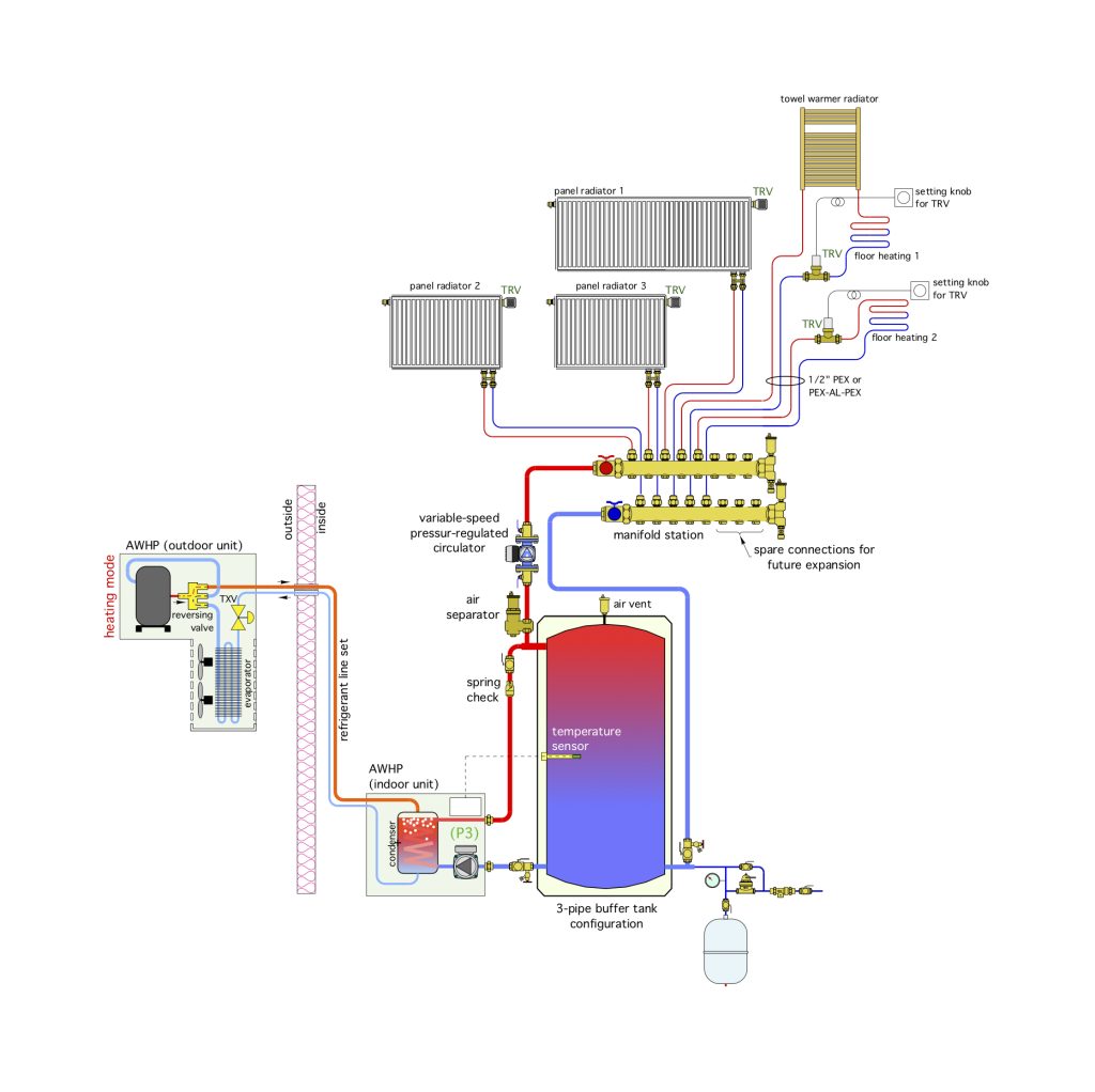
Figure 2. An air-to-water heat pump with a three-pipe buffer tank and highly zoned distribution system.
The heat pump supplies a combination of low temp. panel radiators and radiant floor circuits. The panel rad and the floor circuits have been designed to operate at the same supply water temperature. This eliminates the need for mixing valves. Simpler and less expensive is always preferred when possible.
That’s one of the biggest lessons I’ve learned over 40 years in this industry.
The flow and heat output of each circuit is regulated by a non-electric thermostatic valve. A variable-speed pressure-regulated circulator automatically adjusts speed based on these valves.
The heat pump is turned on and off to maintain the water temperature at the middle of the buffer tank between 100F/38C and 110F/43C.
In addition to buffering the heat pump against short cycling, the tank provides hydraulic separation between the heat pump’s internal circulator and the variable speed distribution circulator.
This system leverages modern concepts that combine for high energy efficiency, reliability, and comfort. Perhaps you can use it on a future project. <>

John Siegenthaler

